
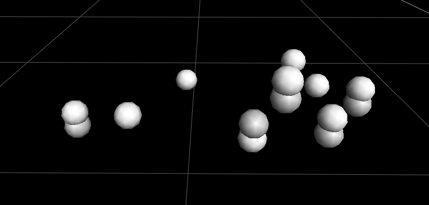
When reconstructing and labelling your data you might have come across the problem of having extra marker trajectories that are almost the same location as what you think are the actual marker locations. Most of the time you can probably figure out which is the real marker and manually correct a few erroneous trajectories. However, with significant duplicates, it’s often best to take a look at your system setup and the root cause of the issue.
 There are a couple of system settings in Nexus that you can change to help resolve this issue:
- Adjust camera Aperture and Thresholds
- Use the Frypan wand wave technique
- Environmental Drift Tolerance
- Minimum Cameras to Start/Continue Trajectory
- Trajectory Startup/Prediction Error
IMPORTANT: You may need to run the Reconstruct pipeline to see the effect of some of these procedures. This will remove any labelling you’ve previously done on the current trial.
Adjust Camera Aperture and Thresholds
One cause could be that a camera has been moved and hasn’t been re-optimised for the new position in the lab space. When this happens, the marker reflections and subsequent centroid fitting may not be as good as it could be, and these duplicate markers appear because of erroneous pixels.
To optimise your camera aperture and threshold
Change the view type in the main window from 3D perspective to Camera. Select the camera in the System pane and in the camera’s Properties change the grayscale mode from Auto to All . The default Threshold setting should be 0.2; we’ll return to that setting later.
- Place a few markers of the same size as your marker set in the capture space.
- Change the view type in the main window from 3D perspective to
- Select the camera in the System pane and in the camera’s Properties change the grayscale mode from Auto to The default Threshold setting should be 0.2; we’ll return to that setting later.
- If you zoom in on the markers in the camera window you should see something like this. If only the yellow crosshairs are there, don’t worry, it could be that you are on a different grayscale mode.
TIP: For captures, you want to make sure Grayscale mode is set to Auto. For setup, you want the Grayscale mode set to All so you can see the individual pixel grayscale blobs and where the crosshairs of the centroid fit.
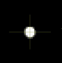 When looking at a marker in the capture volume you want it to look spherical and the pixels to be evenly distributed around the centroid. If not it could be that the aperture is too open (<2.5) or too closed (>11). You want to find a balance of aperture and threshold to get nice round groups of white pixels for the centroid fitting.
TIP: It helps to have an extra set of eyes/hands for this part if there’s someone else in the lab that can help, or you can use the Vicon Control App.
- Lightly loosen the locking screw on the camera lens to allow the aperture adjustment ring to move. The screw does not need to come out, just loose enough for the ring to move. There are two rings on the lens for a Vantage camera:
- The aperture adjusts how open the lens is (more open means more light getting in). Typically you want to start more open (~5.6) and reduce the aperture (8+) to a point where you are getting good reflections from your markers and no background noise.
- Leave the focal length ring on infinity (∞) unless Vicon or Logemas have set it up specifically for your space. The lower values are only really used for specific setups requiring smaller volumes and markers.
Tip: Depending on your specific camera model the position of each ring may look a little different. The ring with the infinity (∞) symbol is always the Focus.
- Use the Threshold setting in the System properties to fine-tune the camera settings until you only see your capture markers clearly. If there are reflective surfaces (floor, devices with metallic cases) that show up as centroids, you can also mask them out during calibration. At this stage, ideally, you want to only see your experimental markers in the space. Any surface or object reflections that are near the edges of the camera 2D view should be ok to mask out. However, any erroneous reflections near the middle of the sensor can be a problem if you mask that area because it could mask an area that your experimental markers pass through.
Tip: Use the aperture for large adjustments and the threshold for small fine-tuning. Adjusting the aperture is preferable to increasing the threshold if you are getting noisy edges to your markers. Making the threshold too high can reduce noise, but potentially removes real data from your markers.
Use the Frypan Wand Wave Technique
There isn’t an established gold standard for the wand wave technique. However, there are some tips and tricks that can help with achieving a more “even” calibration for your whole system.
Common Gait lab designs
Most biomechanics laboratories have a square or rectangular shape with cameras evenly distributed around the sides. This works fine for capturing movement because most marker sets feature markers on the lateral sides of the body.
With this camera layout one of the traps people can fall into is calibrating the room as two “sides”, that is to say, you wave the wand LEDs at one side of the camera and then turn around and face the wand LEDs at the opposite side of the room. When Nexus combines the calibration data to determine the camera locations and orientations in the world coordinate frame, there are essentially two robust side calibrations stitched together by only a few frames of cross-over data. This can produce marker ghosting, where the system thinks there are two markers very close together, but in fact, it is two groups of cameras seeing the same marker. This data is nearly impossible to recover with full data confidence.
 The Frypan wand wave
A helpful movement pattern to add to your wand wave is called (at least what we call) the frypan. At least for part of the time the calibration is running, you hold the wand so the LEDs are facing more toward the ceiling than the side walls. Rather than facing the LEDs toward one side of the cameras, this allows cameras on both sides of the capture volume to see the wand at the same time. Move the wand around in a circular motion, which can be useful to cover the area around the floor or just above a treadmill.
 If you move in a circular pattern around the room, waving the wand within your main capture space (like a Frypan) it will help calibrate cameras on both sides of the volume together for a more robust volume calibration.
Tip: If one camera isn’t calibrating as easily as others, moving toward that camera and facing the wand directly toward it may not improve that camera calibration. At least 2 cameras need to see the wand so you’re better off finding a spot where 2-3 cameras around the troublesome camera can still see the wand.
Environmental Drift Tolerance
It’s common practice in most biomechanics labs to turn the camera system on for half an hour or more before a data collection. This is partly because of the effect temperature can have on the cameras: system or ambient temperature. Once they are powered up and generating heat, the components warm up, expand, and that can affect the data captured if the temperature changes significantly from when the system was calibrated.
In the Reconstruct pipeline properties; there is a setting called Environmental Drift Tolerance, which controls the sensitivity of the camera calibration to temperature change. Increasing the value will reduce the sensitivity (in mm) of the camera calibration to environmental factors like temperature. You will have to run the Reconstruct pipeline to observe a change in this setting post-data collection.
IMPORTANT: This setting should be used as a last resort when you do not have the time or resources to recalibrate the system, or to recover already collected data. Recalibration remains the preferred solution for environmental drift.
TIP: If you think there has been some environmental drift (i.e. live data isn’t looking as good as at the start of your session), you can run a calibration at the end of your collection session and then use this calibration info to get improved reconstructions on the later trials:
- Finish all your data collection
- Run a full calibration and origin set as you normally would
- Capture a new trial called ‘EndofDayRecal’ or something noticeable. There is a .xcp file written for this trial with the new calibration information used
- Replace the .xcp file for the trial you want to use the new calibration for (e.g. (LastTrial.xcp’) with a copy of the new calibration file (i.e. copy/paste ‘EndofDayRecal.xcp’, rename to ‘LastTrial.xcp’). You will have to delete or move (for safe keeping) the original .xcp to match the name.
Minimum Cameras to Start/Continue a Trajectory
When you capture marker data with optical cameras, there’s a minimum of two cameras that need to see a marker to determine its 3D location. When multiple cameras can see a marker for more than one frame it creates a trajectory. A trajectory consists of every frame where the system can see the marker and is certain that is the same marker as the previous frame. The process to form a trajectory depends on Reconstruction parameters such as the Minimum Cameras to Start Trajectory, and Minimum Cameras to Continue Trajectory.
Minimum Cameras to Start Trajectory
This setting controls how many cameras must see the same marker in order to reconstruct a marker position and start a trajectory. The minimum value is two cameras, as with only one camera the system could not determine the depth of the marker position. This value can be increased if there are a large number of unlikely reconstructions being created. If you have a ~20-camera system and are experiencing duplicate markers you may want to increase this value.
Minimum Cameras to Continue Trajectory
This setting controls how many cameras (rays) must see the same marker (centroid) in order to create a reconstruction to continue a recognized trajectory. The minimum value that can possibly create reconstructions is two cameras. The maximum value of this parameter is 30 cameras or the total number of cameras in your system. The value can be decreased if there are gaps in trajectories where reconstruction should be possible when viewed by fewer cameras.
 Trajectory Tracking
Part of creating a trajectory is tracking how the marker moves from one frame to the next. There are two components to this tracking process: how much deviation there is in the first few frames to start a trajectory, and how much deviation there is in the marker’s path from frame to frame.
 Trajectory Startup Error
The deviation allowed (in mm/sec) in a marker’s position at the start of a trajectory. This value is related to the radius within which the current trajectory is matched to a reconstruction in the next frame. If you have a participant running at speed through your capture volume, increase the value to help start a trajectory. Alternatively, if you have dense marker sets such as multi-segment foot models, decrease the value to reduce the odds of confusing the movement of different markers.
Trajectory Prediction Error
The deviation allowed (in mm/sec) in a marker’s position on a trajectory from frame to frame. This value is related to the radius within which the current trajectory is matched to a reconstruction in the next consecutive frame. To help continue trajectories on faster moving markers, increase the value and vice versa.